
Prototypes for assembly validation
Prototypes for assembly validation, 3D printed: the assembly on the bench to check fit, clearance, tool access and sequence before tooling.
When the CAD closes and the assembly does not
An assembly validation prototype is the assembly 3D printed true to the CAD and put together on the bench, to find clearance, interference and sequence problems while the fix is still a line in the file.
- The whole assembly, or just the parts that meet.
- It goes together with real production components.
- Each fix costs a print, not a mould.
Assembly is where mistakes add up
Every part right, the assembly wrong
Every part is within tolerance and the CAD shows no clash. Even so, the spanner will not reach the screw, the cable has no room to bend, or one component has to go in before another. Found on the line, it means rework.
Assemble before you invest
The assembly is printed true to the CAD and goes to the bench with the real parts that already exist. Whoever assembles it finds the problem by hand, and the fix goes back into the file before the mould.
Fit and clearance
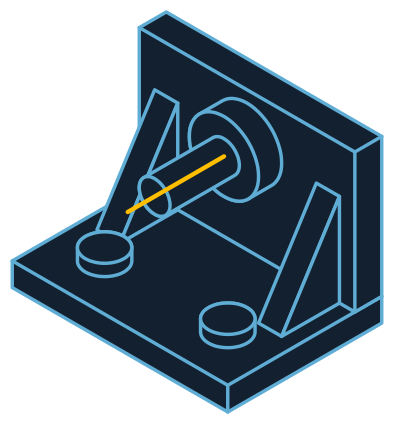
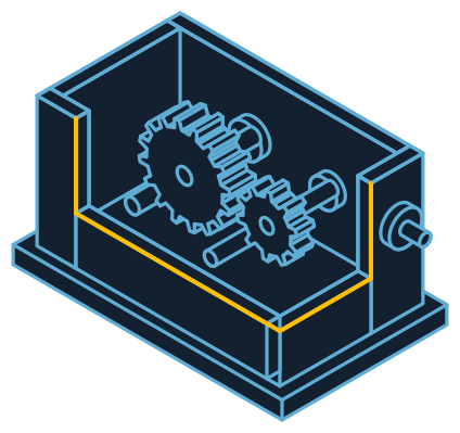
The drawing is a box and lid; the same thinking works for a housing, a panel or any assembly with neighbours.
Illustrative drawing, not to scale. Each project comes from the client’s own file.
- Locating pinsThe lid finds its place by the pins, so alignment shows on the first fit.
- Clearance between partsThe holes in the box show whether the designed clearance lets it go together without forcing.
- Assembly orderThe arrow is the sequence: what has to go in first for the assembly to close.
Spec sheet
- Input
- STL, STEP or OBJ
- What it checks
- Fit, clearance, interference, tool access
- Tolerance
- ±0.1 mm
- Scale
- 1:1
Full spec sheet
- Materials
- Engineering ABS and PETG; PLA for quick checks
- Real parts
- Printed parts go together with production components
- Finish
- On request
- Engineering review
- Feasibility, material and lead time before any commitment
- Delivery
- Made in São Paulo, shipped to every country
Validate in print, in CAD or in the pilot run?
Three points to catch the same mistake, at very different costs.
| Where to validate | What it finds | When | Cost of fixing |
|---|---|---|---|
| Printed prototype | Clearance, tool access and sequence, by hand | Before tooling | A new print |
| CAD analysis | Clashes and volume interference | During design | Low, but it misses what only a hand feels |
| Pilot run | Everything, on production parts | After tooling | Mould changes and a new schedule |
Where assembly validation becomes a solution
Assembly training
The team rehearses the sequence with the printed assembly before the line starts.
Client sign-off
The client fits the assembly to their own equipment and signs off before the batch.
Load testing
Once the fit is right, the part that has to take load goes to a functional prototype.
From the assembly in CAD to the assembly on the bench
The lead time for each round comes with the quote.
File
The assembly in CAD, with the parts that already exist marked.
Engineering review
Which parts to print and what to check at each fit.
Printing
The assembly in engineering material, true to the CAD.
Finishing
Only where a fit needs it; the rest stays raw.
Delivery
The full set of parts, ready for the bench.
What changes lead time and cost
No list price: the engineering review weighs these points.
- Number of parts
- Printing only the parts that meet costs less than the whole assembly.
- Assembly size
- A large assembly comes in pieces, and the joints add to the cost.
- Material
- PLA checks geometry for less; ABS and PETG survive repeated assembly.
- Rounds
- Each fix is a new print of the parts that changed.
Where a printed check is not enough
Better to know before the quote.
Fine production fits
Very small interference depends on the final process. The print checks the arrangement; the fine fit is confirmed in the pilot run.
Parts that need strength
Assembling is not load testing. Snap fits and threads under torque need a functional prototype or the final part.
Very large assemblies
Whatever exceeds the printer’s size comes in pieces. The engineering review says where to split.
Manufacturers that have printed with Tesseract



























Common questions
Do you print the whole assembly or part by part?
The assembly, when the goal is validating it: the interfaces between parts carry the risk. The split comes from the engineering review, based on what needs checking.
Can printed parts be used with real components?
That is the most common use: the printed part stands in for the one that does not exist yet, and the rest of the assembly is production.
How many rounds does it usually take?
It depends on what the first round reveals. The point of the method is that each fix costs a print instead of a tooling change.
How do you know the tool can reach the screw?
By assembling it. The printed set lets the real tool in and shows where it hits, which a volume simulation does not always flag.
Does the CAD not already show interference?
It shows volume clashes. It does not show the hand that cannot get in, the cable with no bend room, or the part that has to go in first. That shows up on the bench.
What sets the price?
What weighs most is how many parts go to print, the size of the assembly and the material. Printing only the parts that meet usually does the job for less. The engineering review shows where to draw the line.
 Trade show
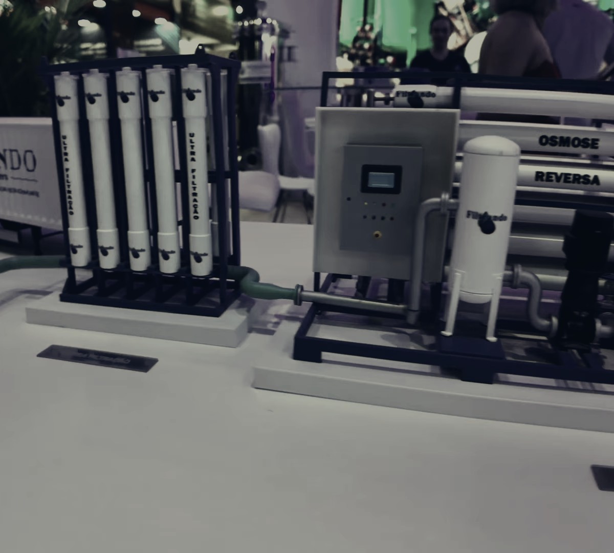
The scale piece goes to the booth instead of the real machine.
 Training
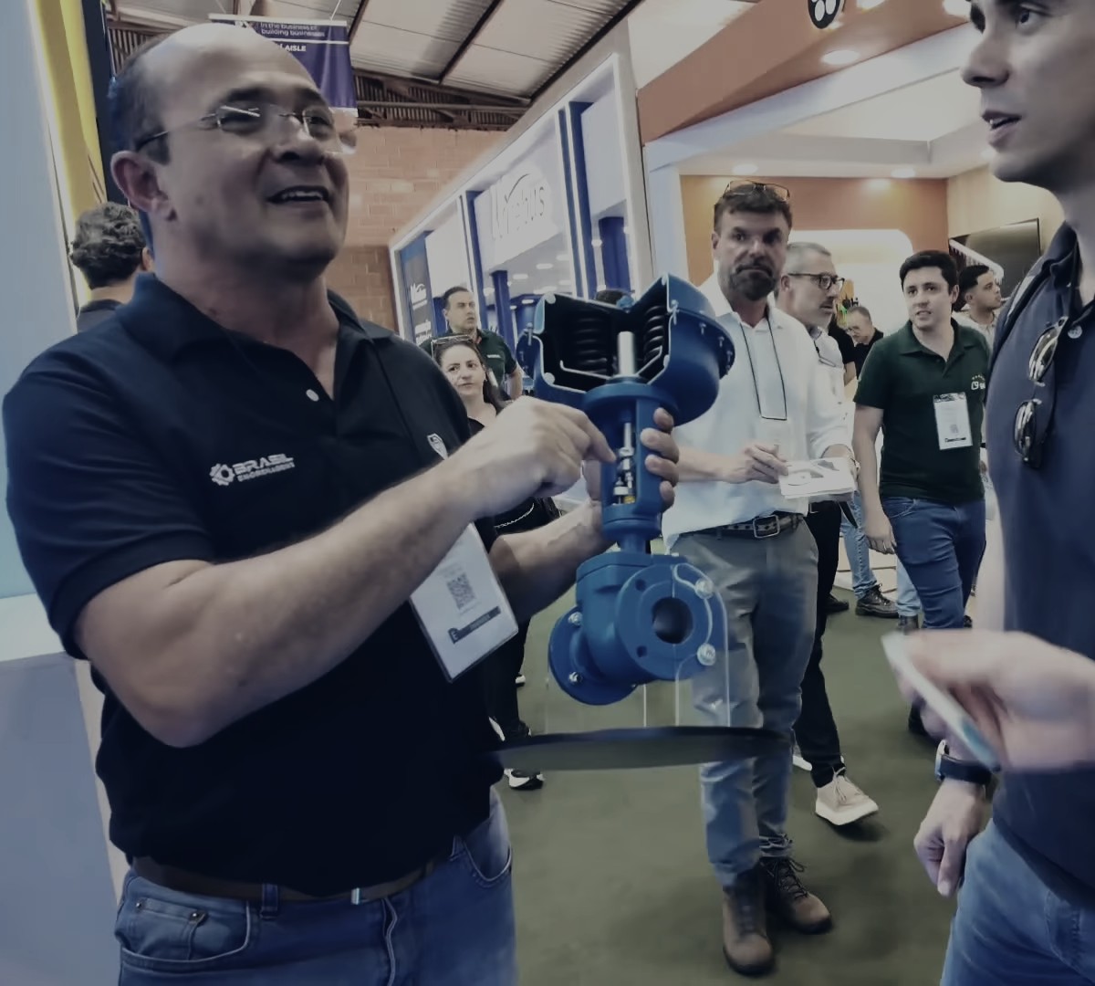
The machine that cannot stop goes into the classroom, cut open.
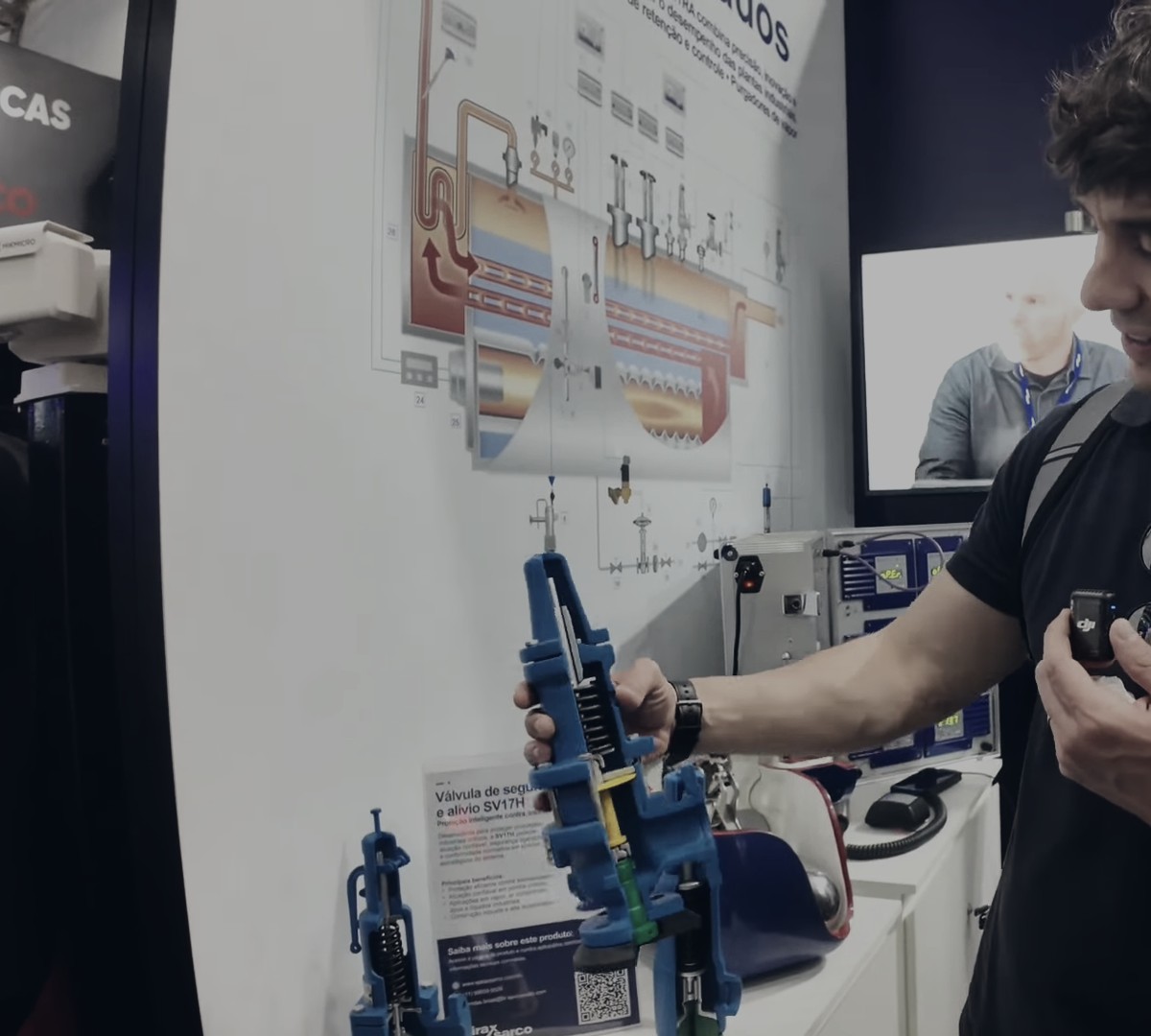 Sales visit
The rep carries in a suitcase what would never fit in one.


An assembly to check before the mould?
Send the assembly. The engineering review comes back within 24 business hours, with the part split, feasibility and lead time.